Author: Sebastiano Grasso, Leonardo Agatino Miccoli, Giusy Gambino, Filippo Scrimizzi,
STMicroelectronics, Catania, Italy
The automotive industry is constantly evolving with an increasing request of automation, safety and power optimization. In this scenario, the usage of DC motors in body applications is playing a significant role. These motors are used in both combustion and electric vehicles for various functions like door lock, window lifts, pumps, steering adjustment, power trunk. Driving the DC motors with dedicated silicon motor drivers offers several advantages in terms of reliability, usage simplicity, monitoring and protection features, and advanced driving capability. An example of implementing advanced and luxury features is the possibility to drive motors with a PWM input signal: varying duty cycle will modulate motor speed and torque. However, the PWM signal can cause significant electromagnetic interference (EMI), leading to issues such as radio frequency interference and signal distortion. In extreme cases, the EMI can have severe impact on the safety of the vehicle, interfering with critical safety systems such as airbags, anti-lock brakes, and electronic stability control, creating serious safety hazards for drivers and passengers. Therefore, it is essential to carefully design and operate the motor and its control circuitry to minimize EMI and ensure a reliable operation of all electronic systems in the vehicle. This can be achieved through a careful component selection, proper grounding and shielding techniques, and the use of adequate filtering that reduces switching noise and other sources of EMI.
Driving Steering Column Motors
Automotive manufacturers are increasingly adopting brushed DC motors for steering columns in vehicles to enhance driving experience, improve driver comfort, and ensure safety. In steering columns, lift and shift motors are commonly used to adjust the steering wheel’s height and position. The lift motor raises or lowers the steering column to accommodate drivers of different heights, while the shift motor moves the steering wheel forward or backward for a more comfortable driving position. A typical block diagram for this application is shown in Fig. 1.
Driving Steering Column Motors
Automotive manufacturers are increasingly adopting brushed DC motors for vehicle steering columns to enhance the driving experience, improve driver comfort, and ensure safety. In steering columns, lift and shift motors are commonly used to adjust the steering wheel’s height and position. The lift motor raises or lowers the steering column to accommodate drivers of different heights, while the shift motor moves the steering wheel forward or backwards for a more comfortable driving position. A typical block diagram for this application is shown in Fig. 1.
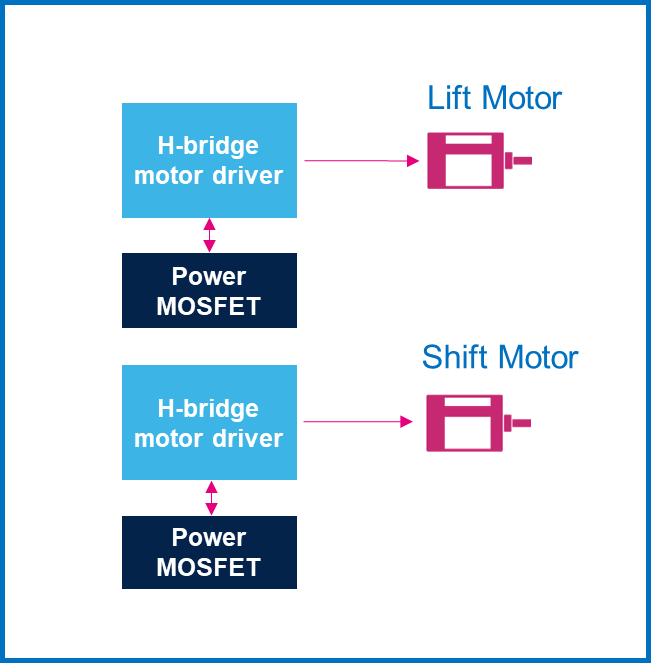
The ST VIPower M0-7 H-bridge family consist of a wide selection of DC motor drivers specifically designed for automotive applications. Integrating into one single package logic functions and power structures, the VIPower M0-7 H-bridges allow driving, protection and fault function, providing advanced diagnostic, protection features and footprint minimization. The VNHD7008AY and VNHD7012AY represent the best fit for driving steering column actuators, the hosted in the powerSSO-36 package makes integration into new or existing designs simple and efficient.
To complete the H-bridge function, the VNHD7008AY/VNHD7012AY need the usage of two external power MOSFETs. The STL76DN4LF7AG and STL64DN4F7AG are high-performance products that leverage STMicroelectronics’ STripFET F7 technology. They are AEC Q101 qualified, ensuring their suitability for use in automotive applications. The dual-island PowerFLAT 5×6 package is another great feature that enables compact designs by saving space on the PCB.
The VNHD7008AY / VNHD7012AY allow to drive both motors in clockwise and counterclockwise modes at a frequency of 20 kHz and pulsed power supply with a duty cycle of 85%.
EMI Tests
To measure EMI within a particular frequency range, a setup that uses a rod monopole antenna is employed in compliance with the international standard CISPR 25. The measurements are conducted in an anechoic chamber to reduce any external interference, as illustrated in the block diagram depicted in Fig. 2.
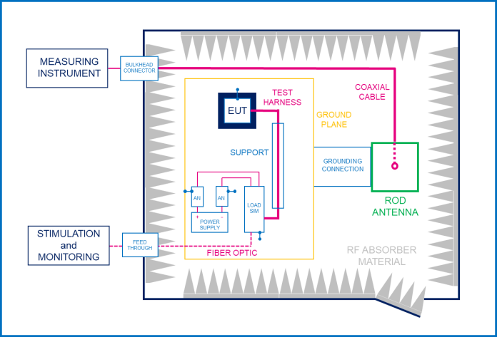
The setup consists of several components, including the equipment under test (EUT), which is locally grounded as required by the test plan, a load simulator (Load sim), an artificial network (AN), and support with a low relative permittivity (εr ≤ 1.4). The rod antenna used in the setup has typical dimensions of 600 mm by 600 mm. This configuration ensures accurate and reliable measurements of EMI, by utilizing an emission test receiver positioned outside the chamber.
The receiver’s parameters are set in accordance with the CISPR 25 standard, as outlined in Tab. 1.
| Service/Band
|
Frequency
[MHz] |
PeakDetection | Quasi-Peak Detection | AverageDetection | ||||||
| BW at-6 dB | Max step size | Min meas. time | BW at-6 dB | Max step size | Min meas. time | BW at-6 dB | Max step size | Min meas. time | ||
| BROADCAST | ||||||||||
| LW | 0.15 to 0.30 | 9 kHz | 5 kHz | 50 ms | 9 kHz | 5 kHz | 1 s | 9 kHz | 5 kHz | 50 ms |
| MW | 0.53 to 1.8 | |||||||||
| SW | 5.9 to 6.2 | |||||||||
| FM | 76 to 108 | 120 kHz | 50 kHz | 5 ms | 120 kHz | 50 kHz | 1 s | 120 kHz | 50 kHz | 5 ms |
| TV Band I | 41 to 88 | |||||||||
| TV Band III | 174 to 230 | |||||||||
| DAB III | 171 to 245 | |||||||||
| TV Band IV/V | 468 to 944 | |||||||||
| DTT | 470 to 770 | 120 kHz | 50 kHz | 5 ms | Does not apply | Does not apply | Does not apply | 120 kHz | 50 kHz | 5 ms |
Tab. 1 Emission parameters of the test receiver (CISPR 25 standard).
The table provided above (Tab. 1) displays different types of broadcasts, which are defined as follows:
- LW: Longwave
- MW: Medium wave
- SW: Short wave
- FM: Frequency modulation
- TV band: Television band
- DAB: Digital audio broadcasting
- DTT: Digital terrestrial television
- SDARS: Satellite digital audio radio service.
Guidelines for EMI Reduction
Experimental results are used to develop guidelines for optimizing EMI in a steering column application that utilizes either the DC motor driver VNHD7008AY or VNHD7012AY.
- Initial Condition
In the original application board, the steering column is not grounded and no compensation network is applied. The emissions are captured using peak and average detectors (as shown in Fig. 3).
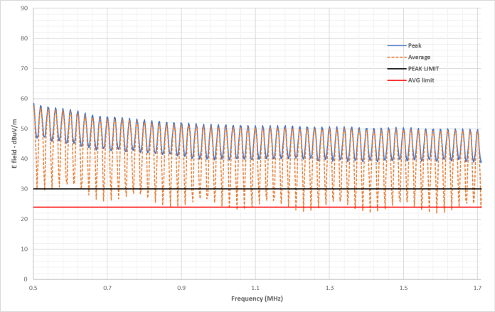
The AM (amplitude modulation) band, which encompasses LW, MW, and SW, is found to have high levels of emissions. The above figure illustrates that these emissions are most prominent in the frequency range of 0.5 MHz to 1.7 MHz and surpass the limit specifications.
2. Ground Connection
One of the guidelines, which has been implemented and experimentally verified, involves directly connecting the steering column body to the system ground. The emission graphs for both average and peak values with this modification are presented in Fig. 4.
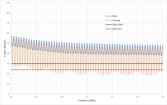
Based on the analysis, it seems that connecting the steering column body to the ground can help improve EMC (Electro-Magnetic Compatibility) performance. However, the emissions are primarily caused by the harmonics of the PWM (Pulse-Width Modulation) signal and the hard and asymmetrical slopes of the rising and falling edges. Filtering the input noise is challenging due to the high current flowing level in the battery line. This means that high saturation current inductor filters would be required, which could impact the final cost of the application platform.
3. Slowing Down the Switching Edges
In order to reduce emissions in the 0.5 MHz – 1.7 MHz band, it is also recommended to slow down the switching edges and to optimize the balance of the rise and fall edge. This can be achieved by implementing several actions, as shown in Fig. 5.
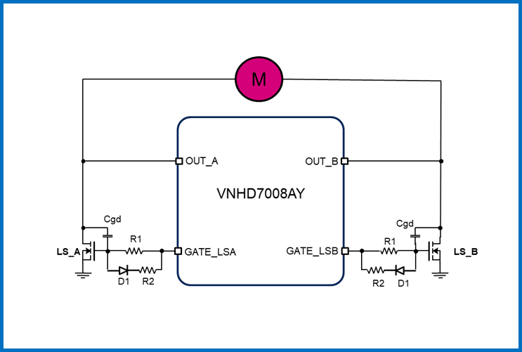
Adding an additional gate-drain capacitor will increase the total gate-drain capacitance and will slow down the switching phase of the LS power MOSFETs. Increasing the MOSFET gate resistance and introducing an asymmetrical gate driving circuitry will allow to balance the rising and falling switching slopes. Modifying the capacitance value of the input filter can further help reduce emissions in this frequency band.
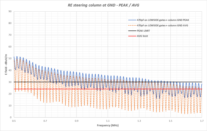
3.1 Extra Gate-Drain Capacitor
By adding an extra gate-drain capacitor to the LS external power MOSFETs, the emissions can be reduced by an average of 10 dBµV/m in the frequency range of 0.5 MHz ~ 0.8 MHz and about 20 dBµV/m between 0.8 MHz and 1.7 MHz, where dBµV/m indicates decibels – voltage level – referenced to 1 microvolt per meter.
This improvement is not affected by whether the steering column body is grounded, but grounding can further reduce electromagnetic interference and improve overall system performance. It is recommended to use a maximum value of 470 pF for the extra gate-drain capacitor to prevent sudden system shutdown. Indeed, increasing the rising switching slope can trigger the VDS (drain-source voltage) protection that is embedded inside the VNHD7008AY / VNHD7012 (specifically designed to protect the motor against short to battery line). Higher values of capacitance (up to 560 pF) could be acceptable but are not suggested, considering the tolerance of capacitance values and variations in the temperature range. A value of 470 pF will ensure a safe margin, accounting for all these factors. The best result that can be achieved with this circuit modification is shown in Fig. 6, which depicts the emissions with the extra gate-drain capacitor and steering column connected to the ground.
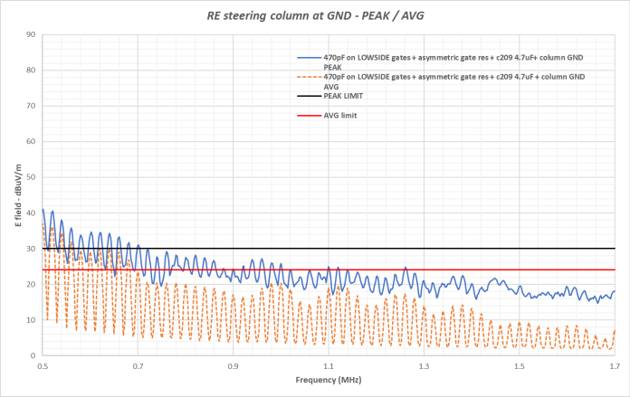
3.2 Asymmetric Gate Driving
This circuit optimization involves increasing the resistance from the output of the H- bridge motor drivers to the gate of the LS MOSFETs and considering the circuit shown below (Fig. 7) for the asymmetrical gate driving.
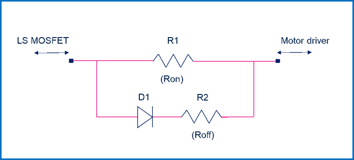
To reduce electromagnetic emissions, there are two solutions that can be implemented. The first solution involves increasing the gate resistance (R1) from 470 Ω to 1 kΩ. The second solution involves adding a diode (D1) with a resistance (R2) set to 470 Ω to achieve asymmetrical gate driving. Additionally, increasing the gate-drain capacitance can result in more balanced switching waveforms with smoother rising and falling edges on the motor’s terminals. These solutions are shown to be effective in reducing emissions in Fig. 8, which displays emission waveforms with the steering column body connected to the ground.
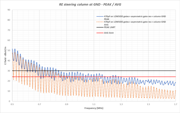
The proposed solution enables the emission levels to remain below the normative limits of the CISPR 25 standard within the frequency range of 0.9 MHz to 1.7 MHz.
To provide a clearer explanation of the effect of the asymmetric gate driver, it is useful to consider some test measurements conducted on an application board loaded with a dummy resistive-inductive (R-L) load:
- 2 Ω resistor with 13 µH inductor.
When a 470 Ohm gate resistor is mounted on the LS MOSFET gates, the falling switching edges are much quicker (about 170 ns) compared to the rising ones (about 800 ns).
By introducing the asymmetric gate driver shown in Fig. 6 with the following values:
- R1 = 1000 Ω
- R2 = 470 Ω
the falling and rising switching shapes are more balanced.
The relevant waveforms are shown in the figure below (Fig. 9), where the green curve is the gate-source voltage (VGS) of the MOSFETs, the red curve is the PWM (Pulse Width Modulation) control voltage (VCONTROL) and the blue curve is the voltage on the load (VDS drain-source voltage of the MOSFETs).
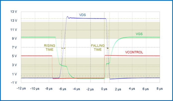
The rising time is reduced due to the lower gate resistance resulting from the parallel of the two resistances R1 and R2 (equal to about 320 Ω), while the fall time is increased up to 270 ns.
In conclusion, the combination of more balanced rise and fall switching times along with slowing down of the switching times (resulting in a reduction of associated harmonics) leads to an overall improvement in emission rate.
3.3 Extra Filtering Capacitance
It is recommended to add an extra capacitor to the input filter with a 1 µH inductor for further reduction of emissions, especially in the lowest frequency range.
The cumulative effects of all suggested modifications are shown in Fig. 10, displaying both peak and average measured spectrum.
There is still a small frequency interval where emissions are above the standard specification limits. These values could be further reduced with an additional input filter, which can increase the performance from a minimum of 10 dBµV/m up to 30 dBµV/m maximum with an impact on the final cost of the application.
Conclusions
The comparison of the emission spectrum of the initial case (blue line) with the suggested solution (yellow line) is shown in the following figure (Fig. 11). It provides a summary of the global improvement achieved.

The suggested modifications to the application can effectively decrease the emission rate of a DC motor control system, ensuring compliance with the CISPR-25 standard specification limits within the 0.5 MHz – 1.7 MHz bandwidth. The table below (Tab. 2) summarizes the average reduction of peak emissions achieved by implementing the different solutions in sequence.
| Conditions | Peak Emission Reduction[dBµV/m] | |
| Low freq(0.5 MHz – 0.8 MHz) | High freq(0.8 MHz – 1.7 MHz) | |
| Ground connection | 2 dBµV/m | 2 dBµV/m |
| Extra gate-drain capacitor | 10 dBµV/m | 20 dBµV/m |
| Asymmetric gate driving | 20 dBµV/m | 25 dBµV/m |
| Extra filtering capacitor | 25 dBµV/m | 30 dBµV/m |
Tab. 2 Mean reductions of peak emissions.
The findings demonstrate the effectiveness of the proposed modifications to the DC motor control system application in reducing the emission rate and ensuring compliance with the CISPR-25 standard specification limits. This is essential for the reliable and safe functioning of the system.
References
[1] R. Kahoul, Y. Azzouz, B. Ravelo, B. Mazari, “New Behavioral Modeling of EMI for DC Motors Applied to EMC Characterization,” IEEE Transactions on Industrial Electronics, Vol. 60, Dec. 2013.
[2] J.M. Poinsignon, P. Matossian, B. Mazari, F. Duval, “Automotive Equipments EMC Modeling for Electrical Network Disturbances Prediction,” Proc. IEEE Int. Symp. EMC, Vol. 1, 2003.
[3] “CISPR 25 IEC, Limits and Methods of Measurement of Radio Disturbance Characteristics for Protection of Receivers used on Board Vehicles,” 2002-2008.
[4] S. Wang, Y.Y. Maillet, F. Wang, R. Lai, F. Luo, D. Boroyevich, “Parasitic Effects of Grounding Paths on Common-Mode EMI Filter’s Performance in Power Electronics Systems,” IEEE Trans. Ind. Electron., Vol. 57, Sept. 2010.


