
A ubiquitous charging infrastructure will be required to support the coming electric vehicle (EV) use surge. Designers are challenged to develop a wide range of infrastructure solutions for use at residences, hotels, shops and restaurants, commercial and industrial sites, parking garages, gas stations, rest stops, and other locations for always available and convenient EV charging. In some cases, users will have the luxury of time and will only need a few kilowatts (kW) of alternating current (AC) charging power over an extended period. In other circumstances, time will be of the essence, and users will demand hundreds of kW of direct current (DC) power to charge EVs in minutes.
Designers need various connector options that can handle low-power AC, high-power DC and a range of power levels in between. Those connectors need to be ergonomic to provide user convenience, and they need to be robust and simple to install to support the needs of EV makers for cost-effective and reliable solutions. The charging handles and power inlets must satisfy the requirements of the combined charging system (CCS) standard, SAE J1772, and IEC 62196.
This article reviews the technical requirements for EV chargers in a range of settings, from low-power AC chargers at residences to high-power charging (HPC) at various commercial locations, including the electrical performance and interface standards and the need for liquid cooling in HPC installations. It then presents a range of AC and DC charging inlets, handles, and cable systems from Phoenix Contact that support the needs of all types of EV charger designs, along with a liquid cooling system for HPC cables and connectors.
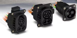
EV charging standards and corresponding connectors have been developed in North America, Europe, and China. The standards in North America and Europe are related to both based on the combined charging system (CCS) standard that combines AC and DC charging in a single inlet on the vehicle. CCS type 1 connectors are prevalent in North America and Korea, and CCS type 2 connectors are found in Europe, the Middle East, South Africa, South America, Australia, New Zealand, and some other areas. China has gone its own way with the GB/T standard that requires separate inlets for AC and DC charging (Figure 1).
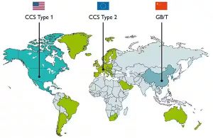
CCS types
There are two versions of the CCS standard, Type 1 and Type 2. Type 1 meets the SAE J1772 and IEC 62196-3 standards and was developed for the North American market. The structure of the AC and DC charging connectors is compatible with a common CCS vehicle inlet.
Type 2 also meets IEC 62196-3 but not SAE J1772. It was originally developed in Europe and has been adopted across several regions, as noted above. Type 2 AC and DC charging connectors are also compatible with a common CCS vehicle inlet.
The GB/T 20234 charging standard is only used in China. In this case, the AC and DC connectors have different interfaces and require that separate inlets be used on the vehicle.
Charging modes
In addition to the physical differences between CCS Type 1 and Type 2 connectors, different charging modes are used in North America and Europe. Lower power modes use the onboard EV charger, while higher power modes rely on external chargers. In addition, higher power levels can have greater thermal challenges and benefit from higher accuracy temperature monitoring.
The North American SAE J1772 standard recognizes three modes or levels:
- Level 1 is intended primarily for residential settings and uses 120 volts AC (Vac) to deliver up to about 1.9 kilowatts (kW).
- Higher voltage 208/240 single phase AC is used by Level 2. That’s called “fast AC charging” and can deliver about 19 kW to the onboard EV charger.
- Level 3 is DC charging using an external DC charger. The basic specification is for 600 VDC at up to 400 amperes (A) for a maximum of 240 kW. Advanced designs can deliver 1 kilovolt DC (kVDC) and 500 A for a total of 500 kW.
Four charging modes are defined by IEC 61851-1. Modes 1, 2, and 3 use the EV’s onboard charger:
- Modes 1 and 2 are for low-power AC charging. Mode 1 cables plug directly into the AC mains outlet, and the available power is limited. Mode 2 also plugs directly into the AC mains but adds an in-cable control and protection device to deliver up to 15 kW with three-phase AC safely.
- Mode 3 is fast AC charging and uses a charging station to deliver up to 120 kW of AC power. Level 3 chargers can optionally include a high-level communications (HLC) protocol between the external AC power source and the onboard charger for charging control.
- Mode 4 is fast DC charging and can deliver several hundred kilowatts directly to the battery. HLC is required in Mode 4 to provide the feedback necessary for charger control.
Thermal protection
Thermal protection is provided in both AC and DC charger cables. For AC charging up to 80 A, a positive temperature coefficient (PTC) thermistor chain is common. It consists of a chain of devices, with one on each contact. Monitoring the resistance values ensures safe shutdown if the limit temperature is exceeded.
Higher accuracy Pt1000 sensors are used on the contacts of high-power chargers to ensure quick response and enable the system to operate consistently at high power levels.
AC inlet and cabling options
For designers of AC charging systems, Phoenix Contact offers a full range of universal charging inlets that can accept AC or DC inputs, and dedicated AC-only inlets that meet the requirements for Type 1 in North America and Type 2 in Europe and are suited for vehicles that don’t require DC charging. These assemblies include a 2-meter power cable and 1-meter cables for the locking actuator, temperature sensor, and communications. They have locking mechanisms, temperature sensors, and dust caps. Examples of cabling for use in IEC 62196-2 and SAE J1772 Type 1 application include:
- Model 1271960 vehicle charging inlet can handle up to 12 kW of single-phase AC power. This inlet is rated for over 10,000 insertion/withdrawal cycles.
- Higher power applications can use the model 1271836, rated for up to 20 kW of single-phase AC power. A locking actuator and protective cap are included.
Phoenix Contact also offers a range of AC charging cables, including:
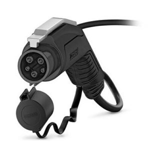
- Model 1277166 for use with SAE J1772 Type 1 vehicle chargers. It has a vehicle charging connector on one end and is open on the other for permanent charger attachment. It includes PTC chain thermal sensing and can handle up to 20 kW of single-phase AC power. It includes a 25-foot cable (Figure 3).
- Model 1627692 mobile AC charging cable with a vehicle charging connector for Type 2 inlets on one end and an infrastructure AC connector on the other for use with Type 2 IEC 62196-2 chargers. This cable assembly can deliver up to 26.6 kW of 3-phase AC power, includes contacts for HLC connections, and is 5 m long.
DC charging cables
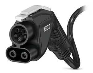
Phoenix Contact offers its CCS C-Line of DC charging cables for medium power charging systems used at private residences, apartment complexes, businesses, and parking facilities. These cables are available in Type 1 and Type 2 designs and the assemblies have a vehicle charging connector with temperature sensors on one end and open cable connections on the other. Examples of Type 1 designs include:
- The 5 m long model 1105880 rated for 40 kW
- The 7 m long model 1236563 rated for 80 kW (Figure 4)
Universal charging inlet
The model 1210900 universal charging inlet works with AC and DC CCS Type 1, IEC 62196-2, and IEC 62196-3 connectors rated for up to 200 A and 1 kVDC, or 80 A and 250 Vac single phase. The DC contacts have two PT1000 thermal sensors, and the AC contacts have a PTC chain thermal sensing scheme.
500 kW DC cabling system
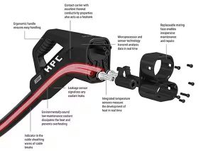
Designers of high-power mode 4 HPC DC charging systems can turn to the 1085658 cabling system that includes a liquid-cooled vehicle connector and cable that can deliver up to 500 A at 1 kVDC. It meets CSS Type 1, SAE J1772, and IEC 62196-3-1 requirements. The system includes sensors for temperature monitoring, cable breaks, and coolant leaks (Figure 5). Temperature monitoring is implemented with two NTCs for the DC contacts and two NTCs for the DC power wires in the cable.
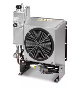
Phoenix Contact also offers a self-contained cooling unit with these DC charging cables. It includes a variable-speed fan and pump to deliver optimized cooling for high-power DC charging systems (Figure 6). The pump and fan operate from 0 VDC to 10 VDC, the fan consumes a maximum of 1.97 A, and the pump requires up to 1.8 A. The cooling solution is a mixture of 50% water and 50% glycol. The cables and wiring are 1.5 meters long. When combined with the 1085658 cabling, the system has a cooling capacity of 600 W for 3 m cables, 800 W for 4 m cables, 900 W for 5 m cables, and 1050 W for 6 m cables.
Summary
A wide range of EV charger styles and power levels will be needed to provide the comprehensive charging infrastructure for broad-based EV adoption. Designers must develop charger designs from low-power 1.9 kW AC chargers that use the internal EV battery charger circuitry, to HPC 500 kW DC chargers with liquid-cooled cabling that bypass the internal charging circuitry and directly charge the batteries. Between those extremes, a wide range of charger power levels and charging modes will be required to support always-available EV charging at private residences and apartment buildings, hotels, shops and restaurants, commercial and industrial sites, parking garages, gas stations, rest stops, and other locations.
Author:
![]()


