
Introduction
There is a growing share of electronics in a car, ranging from infotainment, body and engine controls to advanced driver-assistance modules. Today, premier cars have up to 70 MCUs (Microcontroller Control Units), interconnected by several system buses and exchange thousands of signals between themselves. To put that in business perspective, analysts estimate autonomous chips annual revenue to grow from $11 billion (in 2019) to $29 billion in 2030, representing a revenue of $350 per vehicle by 2030 [1]
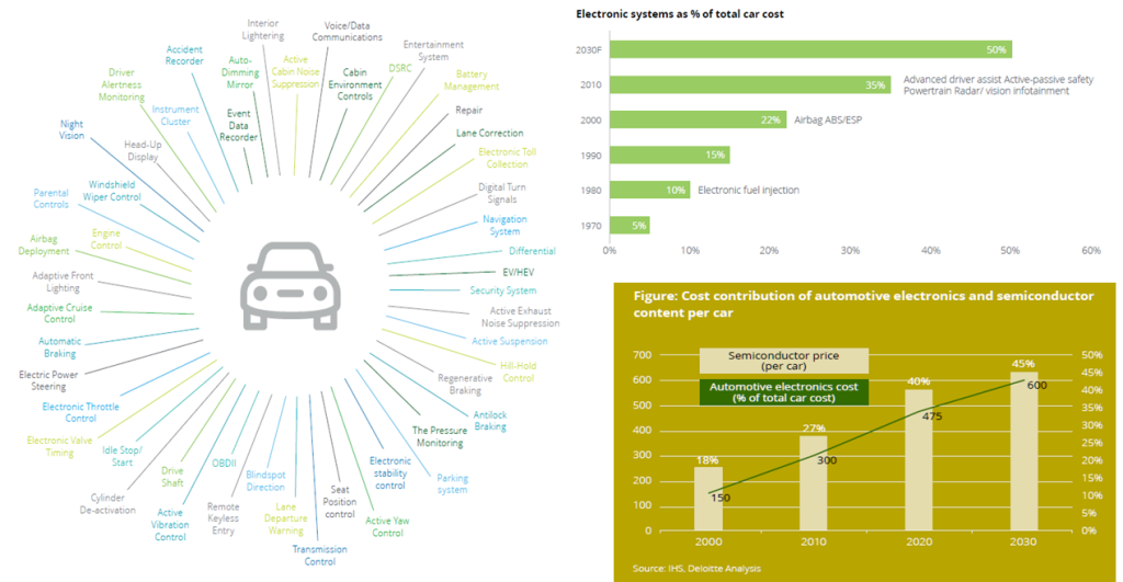
The growing electronics in vehicles enables performance enhancement, better safety, security along with other value-added features. With increased complexity of electronics components including cameras, radars, sensors etc, it is important to put sufficient emphasis on their reliability. A single malfunction of an electronic component can lead to a life-threatening situation.
Semiconductor companies supplying the electronic components subject them to rigorous testing for any functional or manufacturing defects.
Device testing is a well-established process, that requires specific design activity in order to insert proper test infrastructure in the die, with support of dedicated EDA software. It Is categorized as Design for Test (DFT) or more generally as DFx, to include other manufacturability, reliability and yield aspects. However, automotive microcontroller unit (MCU) pose additional challenges and constrains on the testing mechanism, compared to communication, networking or entertainment domains.
In this article we provide an overview of these unique challenges and testing solutions deployed.
Automotive Testing Challenges Overview
- Mission critical application
Automotive unit is a life-sensitive application, both for people inside as well as outside the vehicle, thus there is no room for an error. We can very well imagine the impact, if the air bags do not get deployed at the right time! The level of acceptable defects is expressed by DPPM (Defective Parts Per Million) and Automotive Safety Integrity Levels (ASIL) defined under ISO 26262. While for a consumer grade device, a DPPM number of ~300 may be acceptable, for automotive it has to be close to zero !
Thus automotive MCU requires a very high test-coverage and it is common practice to test almost all design nodes through structural stuck-at (SA) and transition delay(TD) tests. The requirements are slightly relaxed for typical consumer grade devices. It is worth mentioning here that gaining just the last 0.1% coverage, takes significant design efforts and a whopping number of test patterns, thus adding to the test time and test cost. Also, in order to cover all types of possible defects in automotive devices, new fault models are continuously explored and added to the test suits, eg, cell-aware, bridging and small-delay-defect tests.
In addition to the factory testing, the devices are regularly screened for any defects that may have creeped-in during the operating lifecycle. Critical logic and memories are fitted with a self-test capability using LBIST and MBIST respectively, that gets triggered at device booting, shutdown or at regular intervals. The results are monitored by application software and any issue gets raised as an appropriate alarm in the system.
Self-test, however, brings its own design overheads when isolating the test-logic from external interferences to ensure that the functionality is not disturbed, prevention of unknown states (X-sources) to avoid corruption of signatures and test-point usage to increase the controllability and observability of the design.
Primary aim of any self-test technique is to detect in-field failures, hence the execution time requirement for such techniques can be very stringent. Any fault should be detected in a specified time called DTI (Diagnostic Test Interval) otherwise it can prove to be catastrophic for the entire system. This makes self-test implementation like LBIST an uphill task. Due to random nature of Logic Built-In-Self-Test (LBIST) engine, generated by on-chip PRPG (Psuedo Random Pattern Generator), it is sometimes very challenging to get the required fault coverage in the allotted time. This calls for massive test point insertions in the design to improve the controllability and observability for random resistant and hard to detect faults. While this step has been optional for normal ATPG testing, it is an absolute essential for LBIST. Testpoints are inserted for hard-to-detect faults, which usually happen to be in logic with deep combo depths and hence timing critical paths, which pose its own challenges during the backend implementation
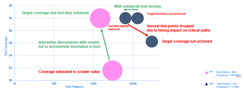
Fig. 2 shows the rigorous exercise done to attain the desired run times for LBIST in two critical IPs for an ST automotive chip. IP1 is a complex design having very high combinational depths. Several iterations with the CAD vendor to enhance the test point insertion algorithms resulted in achieving the required test time and coverage goal. However, few designs like IP2 which achieved the test time goal with enhanced test point insertion flow, created adverse effect on timing, as many control points were added on the critical functional paths. Thus, providing self-test feature in automotive chips can be very iterative and engaging process, with so many conflicting requirements for the DFT engineers.
- Wide environment range, -40 to +150C temp
A car is expected to work seamlessly when driving from the snow-laden mountains right into the scorching dessert or into the humid rain-forests. This puts a lot of pressure when signing-off the device across temperature extremes. The testing also needs to cover these extreme corner conditions yet maintain high production-yields. Automotive qualification includes testing the systems at locations with extreme and opposed conditions like Finland in Winter or Morocco in Summer, etc. to validate the operating range.
Automotive DFT architecture is designed to handle die-to-die and on-chip variance resulting from manufacturing process parameter variations, together with extreme temperature range. The resultant impact to setup and hold timings on design paths, during shift as well as capture phase of scan based testing, are handled through dedicated and robust design structures. This is typically not a need for consumer grade products where the ambient temperature range is roughly 0 to 85C.
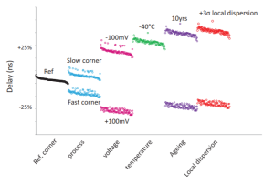
The library characterization, analog models and design sign-off also need to cater to these increased variations and additional margins. This is further aggravated with device aging. As an illustration, Fig 3 depicts how delays get impacted due to variations across PVT (Process, Voltage, Temperature) and ageing. Extreme left on the figure is the reference delay with normal (typical) parameters and subsequent curves show how the delays get skewed with changing parameters.
Device qualification involves samples that are specifically manufactured at different process corners (called matrix-lots) and then tested at every supply-temperature condition. Special circuits, eg on-chip process monitors, are added on each unit to identify the device behavior and to tune (or trim) regulators, oscillators and other critical components accordingly. The data is collected over large number of samples to identify any process drift and to fine-tune the manufacturing, as needed. Scan methods and yield analyzers are leveraged heavily to extract, diagnose and process such data.
- Extended Lifetime – 15yrs
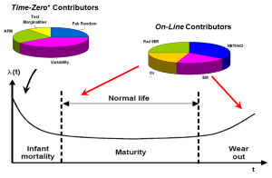
An MCU in the car is required to serve for entire operating life of the car, typically 10-15yrs, without needing any service or replacement. Fig 4 shows typical failure rate change over time. The device qualification needs to account for ageing, long-term reliability and early failure detection.
Every automotive unit is run through stress tests (BurnIN, HVST, VLV etc), unlike many consumer applications where only few sample units are subject to stress tests. The goal of stress tests is to push any weak component to fail upfront, rather than fail in the field.
Some of the ageing manifestations are NBTI (Negative-bias temperature instability), Hot Carrier Injection (HCI) and Time-Dependent Dielectric Breakdown (TDDB) effects [3]. These are typically screened through HTOL (High Temp Operating Life) stress and additional Vmin/Vmax margins during test. For brevity sake, we will skip delving into the details. However, these tests further push the design and test limits. For example, testing at Vmin of 0.9V, while also accounting for tester-equipment uncertainties and on-chip volt-drop, the end nodes of a path may eventually get a voltage below the signoff Vmin. Couple this with PVT parameters and we may be headed at throwing some otherwise good devices (yield impact). We typically add sign-off guard-bands and additional robustness on scan-structure, especially on hold-sensitive shift-paths, to avoid such losses.
Silicon Lifecycle Management (SLM) is another emerging paradigm, in order to maintain the device reliably available through-out the operating lifecycle [4]. SLM leverages test infrastructure, in addition to other sensors like in-situ monitors, to detect and manage issues while in-field. Presence of these additional structures adds to test overheads and require unique solution at each layer. For example, in-situ cells are customized to fully scan-test the monitoring sites, in addition to the functional nodes.
Needless to re-iterate that most consumer applications are exempt from such rigorous tests.
- Standby operation
Certain sensors and control domains remain powered-up through-out, even when the ignition is off.
These devices draw power from the battery in the car and hence are required to keep the power consumption to bare minimum. We would certainly be upset to see the battery all drained and unable to self-start, after parking the car for two-weeks in the garage!
Many automotive devices, especially body applications, are designed with multiple power-domain islands; which sometimes have independent voltage levels as well.
The test architecture is designed to handle the isolation tests, power-controllers, standby operation etc. Multiple supplies also need consideration during low-pin-contact testing.
Networking, server and gaming applications remain powered with an electricity source, hence donot require such low-power designing.
- Security and safety hardening of test logic
Test logic has been demonstrated as a useful tool to extract device secrets by the adversaries. A car in the field contains many secret keys and codes, from chip manufacturer, OEMs, user as well as 3rd party vendors. Access to these assets imposes financial losses as well as risk on the roads (both for the user as well as people around the car), if misused. A device may contain sensitive data from the user, chip vendor as well as 3rd party solution suppliers. Hacking or manipulating a rented car may put the next user at risk or at ransom!
Structural logic, like scan chains, are shown as easy tools to read out device secrets. Thus it is vital that test logic is robustly disabled and cannot be used to launch an attack or read any device secrets [5], even under diagnostic or fail-return scenarios,
At the same time, test logic can also be leveraged to identify any malicious logic or Trojans on the device, inserted during the design or manufacturing process.
In addition to security, test signals also need to be safety compliant. Any soft-error (SET/SUT) in test logic cannot be allowed to impact the device functionality and put it into an unwanted state. Various obfuscation techniques as well as redundancy logic (e.g Triple Module Redundancy) is placed on the test logic and enablement paths to cater to security and safety requirements.
- Volume economics
Automotive qualification and certification is a long, rigorous and expensive process. So a device, once qualified, is used for multiple years, before being upgraded to a new version. Car manufacturers would deploy a single qualified product across multiple models for many years. Automotive chip vendors need to sustain their design, fabrication and testing facilities for a longer period for a single product. All facilities need to consistently perform at same parameters on which device was qualified, without any deviations, thus adding to the maintenance costs.
This places the automotive MCUs into high-volume, low-margin bracket compared to consumer markets. So much so that ‘Automotive grade’ devices are sometimes referred as ‘military-spec products at consumer prices’.
The resulting revenue pressure pushes higher multisite and low-cost-tester solutions, thus adding further complexity to the test architecture and execution.
Conclusion
We talked about some of the unique needs and challenges faced by automotive chips and associated complexities while testing these devices. Testing community has put special architecture and techniques in place, and are constantly evolving, in order to ensure a safe, secure and reliable drive on the roads. It certainly impacts the device and cycle-time costs, but as someone said – if you find testing expensive, try without it !
Authored Article by: Sandeep Jain & Shalini Pathak, STMicroelectronics


