
Somewhere in the world today, an automotive engineer is envisioning an infotainment system for a car that won’t be realized for another five years or more. This includes factoring in the power requirements for applications that exist only as concepts today. As infotainment systems evolve in sophistication and electronic functionality, the number of integrated circuits (ICs) also increases, and the ICs are all sharing power from the 12-V battery.
Designing these power architectures requires the implementation of power conditioning and protection to ensure system functionality across different transient events.
Typical transients
Transients can occur in four common scenarios.
Figure 1 depicts the first scenario which is a load dump event caused by the disconnection of the battery from the alternator during battery charging. A load dump event will cause a voltage increase; for a centralized clamp at the alternator, the maximum voltage would be 35 V.
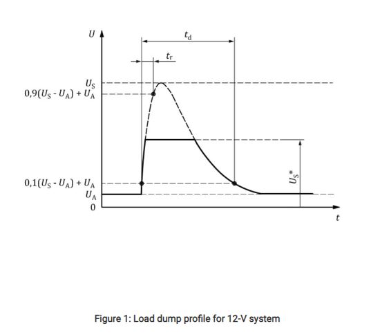
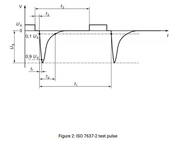
Figure 2 is the second scenario in which a large negative voltage peak (such as International Organization for Standardization [ISO] 7637-2 test pulse 1), will occur in modules in parallel with an inductive load when a power supply disconnection occurs.
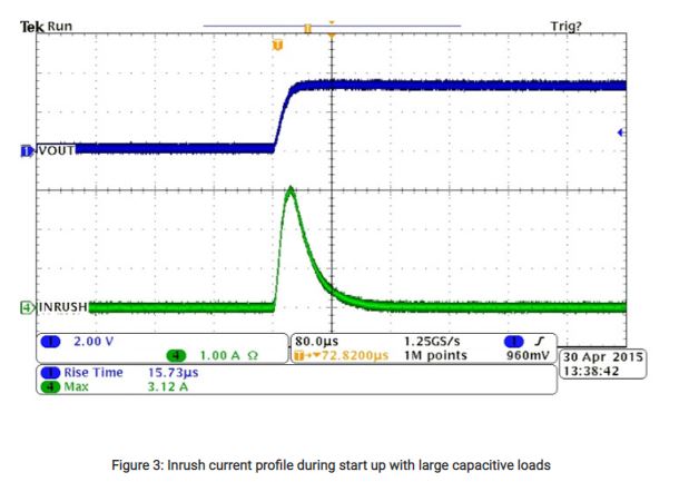
As shown in Figure 3, the third scenario is inrush current during startup caused by the system’s bulk capacitance, which may lead to higher currents as the capacitors are charging.
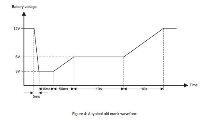
The fourth scenario is a decrease in battery voltage. Figure 4 is a cold crank when the engine starts in a low ambient temperature environment.
Protection against transients
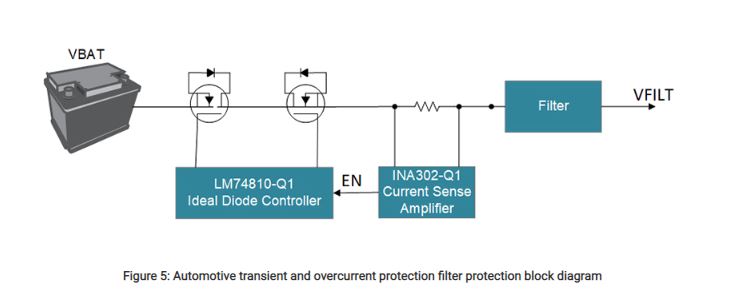
One way to provide transient protection is with an ideal diode controller . As shown in Figure 5, using a current-sense amplifier with an ideal diode controller can provide additional overcurrent protection, resulting in a comprehensive protection solution that precedes any filtering and power conditioning.
Load dump protection
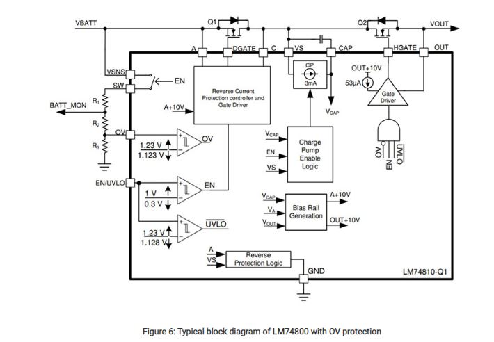
The LM74810-Q1 provides protection from suppressed load dump events through an adjustable overvoltage feature. As shown in Figure 6, the LM74810-Q1 has an OV pin that uses a comparator to signal an overvoltage event. This will turn off the HGATE voltage that drives the Q2 metal-oxide semiconductor field-effect transistor (MOSFET). Adjusting the resistor-divider connected to the OV pin to your preferred threshold enables the use of lower-voltage-rated components downstream that don’t feature the necessary voltage range needed for possible transients at the input.. The LM74810-Q1 device itself has a maximum input rating of 65 V and should remain operational during a 35-V peak transient event.
Negative voltage transient protection
The LM74810-Q1, along with an appropriate MOSFET and input transient voltage suppression (TVS), protects the system from high negative voltage transients such as ISO 7637-2 test pulse 1. If the input voltage is negative the LM74810-Q1 turns off and causes DGATE to pull low. The body diode of Q1 in Figure 6 will then provide reverse voltage protection to the system and prevent any negative current flow. Once the input voltage returns to its nominal state, the LM74810-Q1 turns back on and enables the MOSFETs for normal operation.
Protecting the LM74810-Q1 during the large negative voltage spike caused by ISO 7637-2 test pulse 1 (typically –100 V or more) requires a TVS diode. The input TVS breakdown voltage should be higher than the 35-V load dump condition but lower than the 65-V maximum voltage rating for the LM74810-Q1. For negative voltages, the TVS diode breakdown voltage should be higher than the voltage seen during a reverse battery connection but low enough such that the negative clamping voltage of the TVS does not exceed the of the Q1 MOSFET.
Inrush current limiting
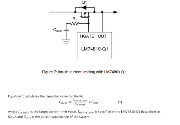
The LM74810-Q1 includes inrush current-limiting functionality to control current at startup. Depending on the amount of capacitance at the output, this feature limits the current to ensure that components do not experience high current beyond safe operation.
As illustrated in Figure 7, adding a resistor-capacitor (RC) to the HGATE of the LM74810-Q1 slows down the HGATE voltage ramp at startup and thus implements inrush current limiting.
Overcurrent protection
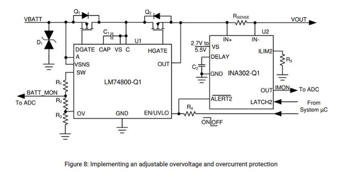
The INA302-Q1 provides overcurrent detection through two independently adjustable threshold comparator outputs. Connecting the active-low comparator output to the enable pin of the LM74810-Q1 allows the MOSFETs to turn off when experiencing an overcurrent condition. The ALERT2 comparator provides the flexibility of having an adjustable delay for the output signal, which may be of use if small current increases may occur during normal operation but you do not want overcurrent protection to trigger during such scenarios. You can adjust the duration of the delay by changing the value of the capacitor placed at the DELAY pin of the device, and adjust the current threshold for the overcurrent event through the INA302-Q1’s ILIM pins; see R5in Figure 8.
Low-voltage transient protection
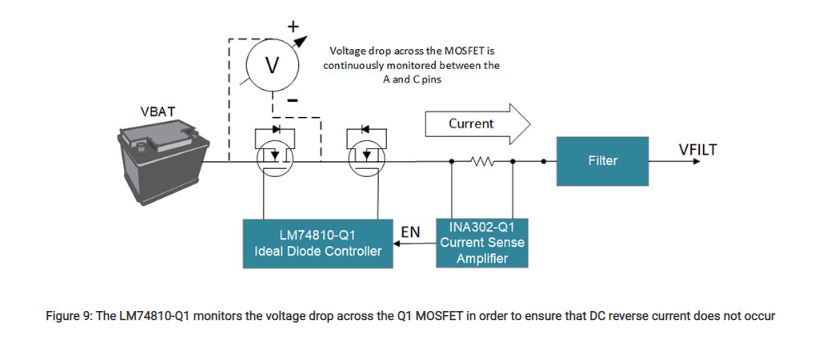
Cold-crank and warm-start events can cause low-voltage transients in the system. Negative current may occur from the input being lower than the output during these events and may be of concern for systems that need to maintain functionality. Because the output voltage will decrease as allowed by the output capacitance present, ensuring that current will not flow back to the battery requires reverse current blocking.
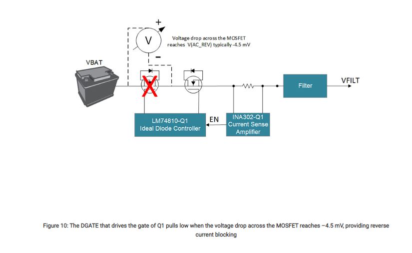
The LM74810-Q1 can provide this kind of protection, as it continuously monitors the voltage drop across the Q1 MOSFET between the A and C pins. As shown in Figures 9 and 10, during normal operation the voltage across Q1 will be positive and current can flow to the load. During instances where reverse current may occur – such as when input is lower than the output– the LM74810-Q1 will rapidly respond when the voltage across Q1 reaches –4.5 mV and will turn off the MOSFET, thus preventing DC reverse current.
Flexibility in the harsh automotive environment
With advanced protection of the system at the input, flexibility is awarded to the designer. These protection devices help drive innovation within automotive with expanded opportunity for choices in the rest of the system without worry for functionality or a lack of protection from harsh electrical environments that can be found in a car.
Additionally, a compact two-device protection system like the one described here offers a significant reduction in total solution size compared to a discrete implementation. A smaller solution size provides even more space and opportunity for innovation for the rest of the infotainment solution.
Beyond protecting your system, we hope this design helps accelerate your design into the next generation.
Courtsey : Texas Instruments


